routing
1) Gateways
Gateways are the key to routing; They are systems through which other networks can be reached. The kind of gateway most people are familiar with is a default gateway, which is the router through which a system will connect to the Internet or any other networks it doesn’t have a more specific route to reach. Gateways are also used for static routing, where other networks must be reached via specific local routers. On most normal networks, gateways always reside in the same subnet as one of the interfaces on a system. For example, if a firewall has an IP address of 192.168.22.5/24, then a gateway to another network would have to be somewhere inside of 192.168.22.x if the other network is reachable through that interface. One notable exception to this is point-to- point interfaces like those used in PPP-based protocols, which often have gateway IP addresses in another subnet because they are not used in the same way.
Gateway Address Families (IPv4 and IPv6)
When working with routing and gateways, the functionality and procedures are the same for both IPv4 and IPv6 addresses, however all of the addresses for a given route must involve addresses of the same family. For example, an IPv6 network must be routed using an IPv6 gateway/router. A route cannot be created for an IPv6 network using an IPv4 gateway address. When working with gateway groups,the same restriction applies; All gateways in a gateway group must be of the same address family.
Managing Gateways
Before a gatway can be utilized for any purpose, it must be added to the firewall configuration. If a gateway will be used for a WAN-type interface, it can be added on the configuration page for that interface , or it may be added first manually and then selected from the drop-down list on the interface configuration.
Dynamic interface types such as DHCP and PPPoE receive an automatic gateway that is noted as Dynamic in the gateway list. The parameters for such gateways can be adjusted the same as the parameters for a static gateway, but a dynamic gateway may not be deleted.
put image
Gateway Settings
When adding or editing a gateway, a screen is presented that lists all of the options for controlling gateway behavior. The only required settings are the Interface, the Name, and the Gateway (IP address).
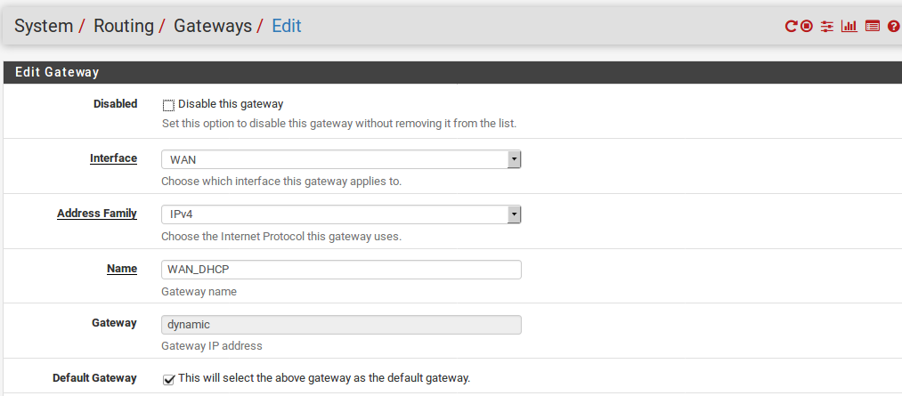
Interface
The interface through which the gateway is reached. For example, choose the WAN interface here.
Address Family
Either IPv4 or IPv6, depending on the type of address for this gateway.
Name
The Name for the gateway, as referenced in the gateway list, and various drop-down and other selectors for gateways. It can only contain alphanumeric characters, or an underscore, but no spaces. For example: WANGW, GW_WAN, an WANGATE are valid but WAN GW is not allowed.
Gateway
The IP address of the gateway. As mentioned previously, this must reside in a subnet directly configured on the selected Interface.
Default Gateway
When selected, this gateway is treated as the default gateway for the system. The default gateway is the gateway of last resort. It is used when there are no other more specific routes. The firewall can have one IPv4 default gateway and one IPv6 default gateway.
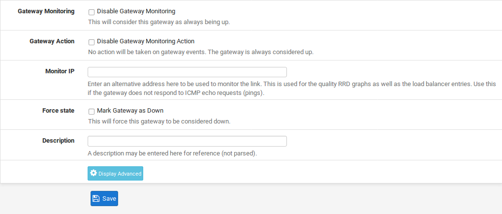
Disable Gateway Monitoring
By default, the system will ping each gateway once per second to monitor latency and packet loss for traffic to the monitored IP address. This data is used for gateway status information and also to draw the Quality RRD graph. If this monitoring is undesirable for any reason, it may be disabled by checking Disable Gateway Monitoring. Note that if the gateway status is not monitored, then Multi-WAN will not work properly as it cannot detect failures.
Monitor IP
The Monitor IP address option configures the IP address used to determine the gateway status. By default the system will ping the gateway IP address. This is not always desirable, especially in the case where the gatewayIP address is local, such as on a Cable modem or DSL CPE. In cases such as that it makes more sense to ping something farther upstream, such as an ISP DNS server or a server on the Internet. Another case is when an ISP is prone to upstream failures, so pinging a host on the Internet is a more accurate test to determine if a WAN is usable rather than testing the link itself. Some popular choices include Google public DNS servers, or popular web sites such as Google or Yahoo. If the IP address specified in this box is not directly connected, a static route is added to ensure that traffic to the Monitor IP address leaves via the expected gateway. Each gateway must have a unique Monitor IP address.
The status of a gateway as perceived by the firewall can be checked by visiting Status > Gateways or by using the Gateways widget on the dashboard. If the gateway shows Online, then the monitor IP address is successfullyreturning pings.
Force State
When Mark Gateway as Down is checked, the gateway will always be considered down, even when pings are returned from the monitor IP address. This is useful for cases when a WAN is behaving inconsistently and the gateway transitions are causing disruption. The gateway can be forced into a down state so that other gateways may be preferred until it stabilizes.
Description
An optional Description of the gateway entry for reference. A short note about the gateway or interface it’s used for may be helpful, or it may be left blank.
Advanced
Several parameters can be changed to control how a gateway is monitored or treated in a Multi-WAN scenario. Most Display Advanced button. If users will not need to alter these values. To access the advanced options, click the any of the advanced options are set, this sectionis automatically expanded. For more information on using multiple WAN connections.
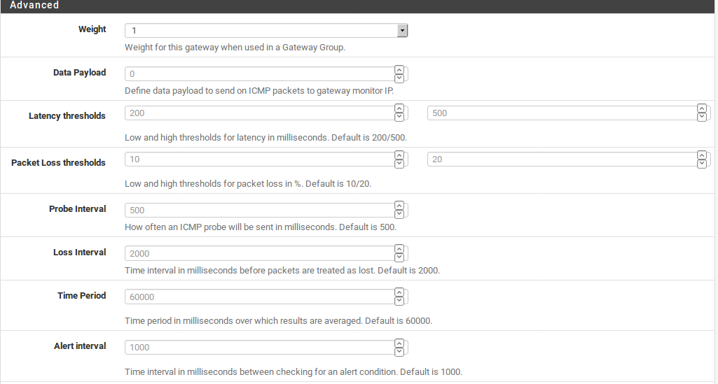
Weight
When using Multi-WAN, if two WANs have different amounts of bandwidth, the Weight parameter adjusts the ration at which the WANs are used. For example if WAN1 has 5Mbit/s and WAN2 has 10Mbit/s, weight WAN1 as 1 and WAN2 as 2. Then for every three connections that go out,one will use WAN and two will use WAN2. Using this method, connections are distributed in a way that is more likelyto better utilize the available bandwidth. Weight from1to 30 may be chosen.
Data Payload
To conserve bandwidth, the dpinger daemon sends a ping with a payload size of 0 by default so that no data is contained within the ICMP echo request. However, in rare circumstances a CPE, ISP router, or intermediate hop may drop or reject ICMP packets without a payload. In these cases, set the payload size above 0. Usually a size of 1 is enough to satisfy affected equipment.
Latency Thresholds
The Latency Thresholds fields control the amount of latency that is considered normal for this gateway. This value is expressed in milliseconds (ms). The value in the From field is the lower boundary at which the gatewaywould be considered in a warning state, but not down. If the latency exceeds the value in the To field, it is considered down and removed from service. The proper values in these fieldscan vary depending on what type of connection is in use, and what ISP or equipment is between the firewall and the monitor IP address. The default values are From 300 and To 500.
Some other common situations may require adjusting these values. For instance some DSL lines run fine even at higher latency, so increasing the To parameter to 700 or more would lower the number of times the gateway would be considered down when, in fact, it was operating acceptably. Another example is a GIF tunnel to a provider such as he.net for IPv6. Due to the nature of GIF tunnels and load on the tunnel servers, the tunnel could be working acceptably even with latency as high as 900 msas reported by ICMP ping responses.
Packet Loss Thresholds
Similar to Latency Thresholds, the Packet Loss Thresholds control the amount of packet loss to a monitor IP address before it would be considered unusable. This value is expressed as a percentage, 0 being no loss and 100 being total loss. The value in the From field is the lower boundary at which the gateway would be considered in a warning state, but not down. If the amount of packet loss exceeds the value in the To field, it is considered down and removed from service. The proper values in these fields can vary depending on what type of connection is in use, and what ISP or equipment is between the firewall and the monitor IP address. The default values are From 10 and To 20.
As with latency, connections can be prone to different amounts of packet loss and still function in a usable way, especially if the path to a monitor IP address drops or delays ICMP in favor of other traffic. We have observed unusable connections with minor amounts of loss, and some that are usable even when showing 45% loss. Ifloss alarms occur on a normally functioning WAN gateway, enter higher values in the From and To fields until agood balance for the circuit is achieved.
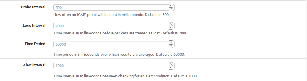
Probe Interval
The value in the Probe Interval field controls how often a ping is sent to the monitor IP address, in milliseconds. The default is to ping twice per second (500 ms). In some situations, such as links that need monitored but have high data charges, even a small ping every second can add up. This value can be safely increased so long as it less than or equal to the Alert Interval and also does not violate the constraint on the Time Period listed below. Lower values will ping more often and be more accurate, but consume more resources. Higher values will be less sensitive to erratic behavior and consume less resources, at the cost of accuracy.
Note
The quality graph is averaged over seconds, not intervals, so as the Probe Interval is increased the accuracy of the quality graph is decreased.
Loss Interval
Time in milliseconds before packets are treated as lost. The default is 2000 ms (2 seconds). Must be greater than or equal to the High Latency Threshold. If a circuit is known to have high latency while operating normally, this can be increased to compensate.
Time Period
The amount of time, in milliseconds, over which ping results are averaged. The default is 60000 (60 seconds, one minute). A longer Time Period will take more time for latency or loss to trigger an alarm, but it is less prone to be affected by erratic behavior in ping results.
The Time Period must be greater than twice the sum of the Probe Interval and Loss Interval, otherwise there may not be at least one completed probe.
Alert Interval
The time interval, in milliseconds, at which the daemon checks for an alert condition. The default value is 1000 (1 second). This value must be greater than or equal to the Probe Interval, because an alert could not possibly occurr between probes.
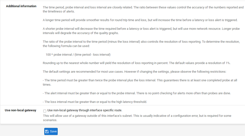
Use Non-Local Gateway
The Use non-local gateway through interface specific route option allows a non-standard configuration where a gateway IP address exists outside of an interface subnet. Some providers attempting to scrape the bottom of the IPv4 barrel have resorted to this in order to not put a gateway into each customer subnet. Do not activate this option unless required to do so by the upstream provider.
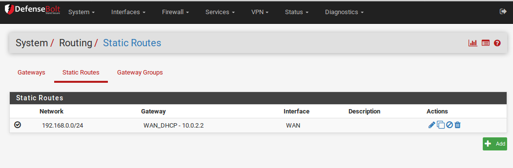
2) Static Routes
Static routes are used when hosts or networks are reachable through a router other than the default gateway. DefenseBolt knows about the networks directly attached to it, and reaches all other networks as directed by its routing table. In networks where an internal router connects additional internal subnets, a static route must be defined for that network to be reachable. The routers through which these other networks are reached must first be added as gateways. See Gateways for information on adding gateways.
Static routes are found under System > Routing on the Static Routes tab.
Managine Static Routes
To add a route: - Navigate to System > Routing on the Routes tab
Add to create a new static route
- Fill in the configuration as follows:
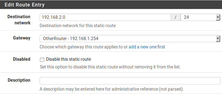
Destination Network Specifies the network and subnet mask that is reachable using this route.
Gateway Defines the router through which this network is reached.
Disabled Check if the static route should not be used, only defined.
Description Some text to describe the route, its purpose, etc.
- Click Save
- Click Apply Changes
Example Static Route
Figure Static Routes illustrates a scenario where a static route is required.
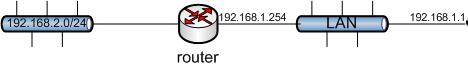
Because the 192.168.2.0/24 network in Figure Static Routes is not on an interface directly connected to DefenseBolt, a static route is needed so the firewall knows how to reach that network. appropriate static route for the above diagram. As mentioned earlier, before a static route may be added a gateway must first be defined.
Firewall rule adjustments may also be required. If custom LAN rules are used, they must allow traffic to pass from a source of the networks reachable via static routes on LAN.
Bypass Firewall Rules for Traffic on Same Interface
In many situations when using static routes, traffic ends up routing asymmetrically. This means the traffic will follow a different path in one direction than the traffic flowing in the opposite direction. Take Figure Asymmetric Routing.
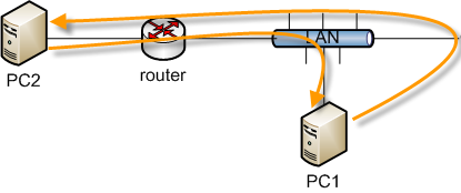
Traffic from PC1 to PC2 will go through DefenseBolt since it is the default gateway for PC1, but traffic in the opposite direction will go directly from the router to PC1. Since DefenseBolt is a stateful firewall, it must see traffic for the entire connection to be able to filter traffic properly. With asymmetric routing such as this example, any stateful firewall will drop legitimate traffic because it cannot properly keepstate without seeing traffic in both directions. This generally only affects TCP, since other protocols do not have a formal connection handshake the firewall can recognize for use in state tracking.
In asymmetric routing scenarios, there is an option that may be used to prevent legitimate traffic from being dropped. The option adds firewall rules which allow all traffic between networks defined in static routes using a more permissive set of rule options and state handling. To activate this option:
- Click System > Advanced
- Click the Firewall/NAT tab
- Check Bypass firewall rules for traffic on the same interface
- Click Save
Alternatively, firewall rules may be added manually to allow similar traffic. Two rules are needed, one on the interface tab where the traffic enters (e.g. LAN) and another on the Floating tab:
- Navigate to Firewall > Rules
- Click the tab for the interface where the traffic willenter (e.g. LAN) add a new rule to the top of the list
- Use the following settings:
Protocol TCP
Source The local systems utilizing the static route (e.g. LAN Net)
Destination The network on the other end of the route TCP Flags Check Any flags (Under Advanced Features) State Type Sloppy State (Under Advanced Features)
- Click Save
Click the Floating tab Add a new rule to the top of the list
- Click
- Use the following settings:
Interface The interface where the traffic originated (e.g. LAN) Direction Out
Protocol TCP
Source The local systems utilizing the static route (e.g. LAN Net) Destination The network on the other end of the route TCP Flags Check Any flags (Under Advanced Features)
State Type Sloppy State (Under Advanced Features)
- Click Save
If additional traffic from other sources or destinations is shown as blocked in the firewall logs with TCP flags such as “TCP:SA” or “TCP:PA”, the rules may be adjusted or copied to match that traffic as well.
Note
If filtering of traffic between statically routedsubnets is required, it must be done on the router andnot the firewall since the firewall is not in a position on the network where it can effectively control that traffic.
ICMP Redirects
When a device sends a packet to its default gateway, and the gateway knows the sender can reach the destination network via a more direct route, it will send an ICMPredirect message in response and forward the packet asconfigured. The ICMP redirect causes a route for that destination to be temporarily added to the routing table of the sending device, and the device will subsequently use that more direct route to reach that destination.
This will only work if the client OS is configured to permit ICMP redirects, which is typically the case by default.
ICMP redirects are common when static routes are present which point to a router on the same interface as client PCs and other network devices. The asymmetric routing diagram from the previous section is an example of this. ICMP redirects have a mostly undeserved bad reputation from some in the security community because they allow modification of a client routing table. However they are not the risk that some imply, as to be accepted, the ICMP redirect message must include the first 8 bytes of data from the original datagram. A host in a position to see that data and hence be able to successfully forge illicit ICMP redirects is in a position to accomplishthe same end result in multiple other ways
Routing Public IP Addresses
This section covers the routing of public IP addresses where a public IP subnet is assigned to an internal interface on a single firewall deployment.
See also:
If a High Availability cluster is in use, see Providing Redundancy Without NAT.
IP Assignments
At least two public IP subnets must be assigned by the ISP. One is for the WAN of the firewall, and one for the inside interface. This is commonly a /30 subnet for the WAN, with a second subnet assigned for the internal interface. This example will use a /30 on WAN as shown in Table WAN IP Block and a /29 public subnet on an internal OPT interface as shown in Table Inside IP Block
WAN IP Block
| 192.51.100.64/30 | |
| IP Address | Assigned TO |
| 198.51.100.56 | ISP router(Default gateway) |
| 198.51.100.66 | DefenseBolt Wan interface Ip |
Inside IP Block
| 192.0.2.128/29 | |
| IP Address | Assigned To |
| 192.0.2.129 | DefenseBolt OPT interface |
| 192.2.0.130 | |
| 192.0.2.131 | |
| 192.0.2.132 | |
| 192.0.2.133 | |
| 192.0.2.134 | |
Interface Configuration
First configure the WAN and OPT interfaces. The LAN interface can also be used for public IP addresses if desired. In this example, LAN is a private IP subnet and OPT1 is the public IP subnet.
Configure WAN
Add the IP address and gateway accordingly. Figure WAN IP and Gateway Configuration shows the WAN configured as shown in Table WAN IP Block.
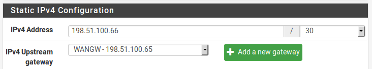
- WAN IP and Gateway Configuration
Configure OPT1
Now enable OPT1, optionally change its name, and configure the IP address and subnet mask. Figure Routing OPT1 Interface Configuration shows OPT1 configured as shown in Table Inside IP Block.
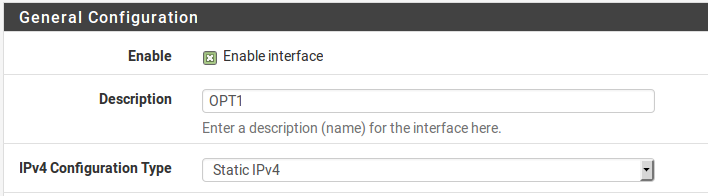
- Routing OPT1 Interface Configuration
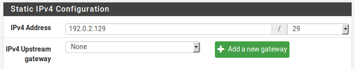
- Routing OPT1 IP Address Configuration
NAT Configuration
The default of translating internal traffic to the WAN IP must be overridden when using public IP addresses on an internal interface.
- Browse to Firewall > NAT
- Click the Outbound tab
- Select Hybrid Outbound NAT rule generation
- Click Save
add a new rule to the top of the list with the following settings:
Do not NAT Checked, so that NAT will be disabled
Interface WAN Protocol Any Source Network, enter the local public IP subnet, 192.0.2.128/29
Destination Any
- Click Save
This will override the default automatic rules which translate all traffic from local interfaces leaving the WAN interface to the WAN IP address. Traffic sourced from the OPT1 network 192.0.2.128/29 is not translated because of the manually added rule excluding it from NAT. This configuration maintains the automatic behavior for other internal interfaces, so that the advantages of automatic outbound NAT rules are not lost. This configuration is shown in Figure Outbound NAT Configuration.
If public IP addresses are used on all local interfaces, then set Disable Outbound NAT rather than using Hybrid mode
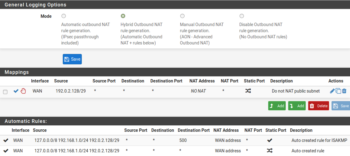
- Outbound NAT Configuration
Firewall Rule Configuration
The NAT and IP address configuration is now complete. Firewall rules will need to be added to permit outbound and inbound traffic. Figure OPT1 Firewall Rules shows aDMZ-like configuration, where all traffic destined for the LAN subnet is rejected, DNS and pings to the OPT1 interface IP address are permitted, and HTTP is allowed outbound.
To allow traffic from the Internet to the public IP addresses on an internal interface, add rules on the WAN using the public IP addresses as the Destination. Figure WAN Firewall Rules shows a rule that allows HTTP to 192.0.2.130, one of the public IP addresses on the internal interface as shown in Table Inside IP Block.
After configuring the firewall rules as desired, the setup is complete.
Note
Traffic will flow from LAN to this public subnet by default without NAT. If this behavior is not desired, adjust
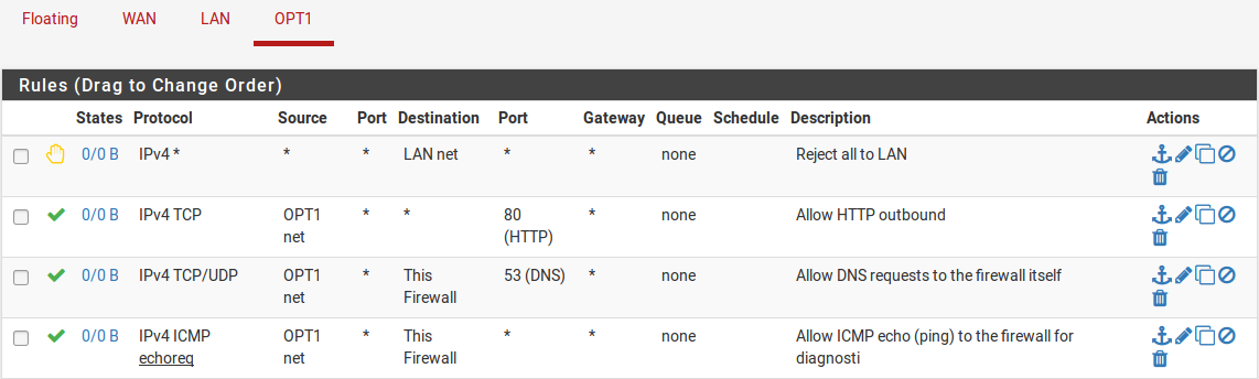
- OPT1 Firewall Rules

WAN Firewall Rules
the LAN firewall and NAT rules accordingly. Additionally, policy routing may need to be bypassed to allow from LAN to this interface.
Routing Protocols
At the time of this writing, three routing protocols are supported with pfSense: - RIP (Routing Information Protocol) - BGP (Border Gateway Protocol) - OSPF (Open Shortest Path First).
This section is light on details, and presumes understanding of the routing protocols as a prerequisite. An indepth discussion of routing protocols is outside the scope of this book.
RIP
RIP is part of the routed package. To install it:
- Navigate to System > Package Manager
- Click Available Packages
- Locate routed in the list, or search for it.
- Click the pluse butten Install to the right of the routed package entry.
- Click right butten Confirm
- Wait for the installation to complete
- Navigate to Services > RIP
To configure RIP:
Check the Enable RIP box
- Choose the Interfaces RIP will listen and send routing updates on
- Select the RIP version
- Enter a RIPv2 password if RIPv2 is in use and requires a password on the network.
- Click Save
RIP will immediately launch and start sending and receiving routing updates on the specified interfaces.
BGP
A BGP package using OpenBGPD from OpenBSD is available. To install it: - Navigate to System > Package Manager
- Click Available Packages
- Locate OpenBGPD in the list, or search for it
click the pluse button Install to the right of the OpenBGPD package entry.
click right butten Confirm
- Wait for the installation to complete
- Navigate to Services > OpenBGPD
BGP is a complex beast, and describing it in detail is outside the scope of this book. Configuration of OpenBGPD on DefenseBolt is straight forward for those with knowledge of BGP. During development of this package, we relied on O’Reilly’s BGP book and recommend it for anyone looking to deploy BGP.
The general form of configuration for the OpenBGPD package is:
- Configure a group on the Group tab with the remote AS
- Configure one or more neighbors on the Neighbors tab as members of the defined Group
- Configure the Settings tab as desired for the local AS and networks to announce.
OSPF
An OSPF package using the Quagga routing daemon is also available. As with BGP, to install it:
- Navigate to System > Package Manager
- Click Available Packages
- Locate Quagga_OSPF in the list, or search for it
- Click the pluse butten Install to the right of the Quagga_OSPF package entry.
click right butten Confirm
- Wait for the installation to complete
- Navigate to Services > Quagga OSPF
OSPF is also a fairly complex routing protocol, though not as complex to setup as BGP can be. The details of configuring OSPFD are also outside the scope of this book, though for someone accustomed to OSPF the configuration options found in the GUI will be familiar.
The general form of configuration for the Quagga OSPF package is:
- Add interfaces as needed, with local interface subnets being marked passive, and those facing other OSPF routers as active.
- Configure the general settings as needed with the router ID, area ID, and so on.