OPENVPN
How To Setup A Site To Site VPN On DefenseBolt
First thing’s first. Here is the addressing scheme of both of my pfsense routers and their subnets. I have substituted my public WAN ip addresses for security.
Router A, (setup as OpenVPN server, located at datacenter)
WAN IP Address: 74.51.1.1 LAN IP Address: 10.0.0.1 LAN Subnet: 10.0.0.0/8
Router B (setup as OpenVPN client, located at home)
WAN IP Address: 108.50.10.5 LAN IP Address: 192.168.1.1 LAN Subnet: 192.168.1.0/24
One side will be configured as a client, and the other as a server. It doesn’t really matter which is which, but if you are connecting more than two sites, it would probably be a good idea to put the “server” on the fastest, most reliable connection. In my scenario, that would be the system at the datacenter. The pfsense documentation recommends shared key mode for site to site VPNs, unless there are more than 6 sites.
A firewall rule is required on the server node to allow traffic through to the interface and port where the server is running. If not, the traffic will be block and the VPN will never connect. If you need to filter certain traffic within the VPN connection, you can do this by adding rules under the OpenVPN tab, located at Firewall > Rules.to check in :mod: ‘Tunnel Settings’like way
First connect to the web interface on Router A, the server. Go to the VPN > OpenVPN Servers tab, and then click + to create a new server.
After clicking + you should see this page.
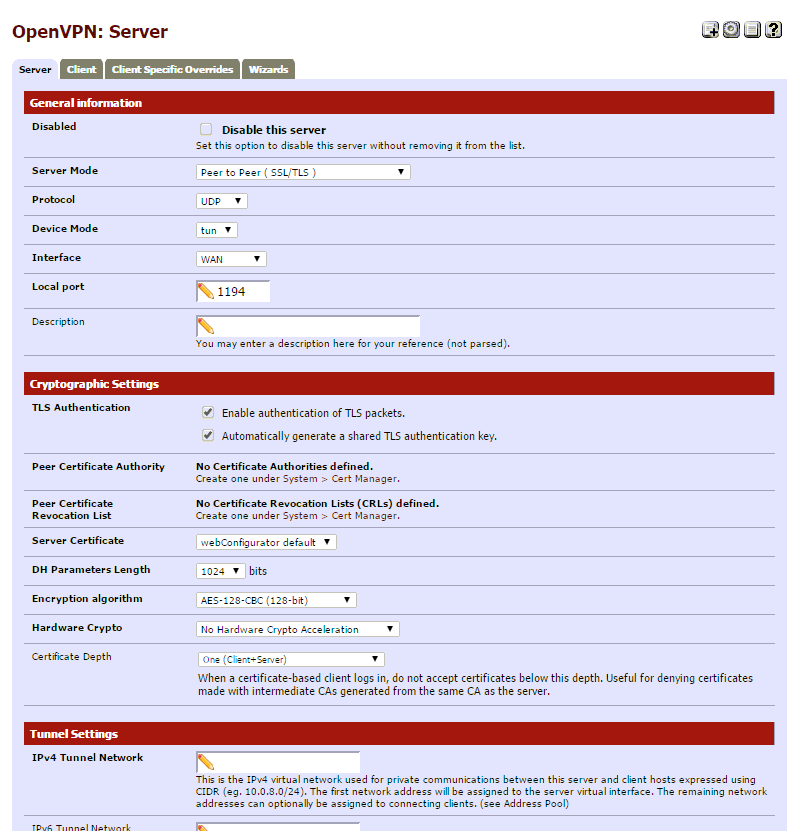
The configuration is separated into four categories.
- General Information
- Cryptographic Settings
- Tunnel Settings
- Advanced Configuration
We will start with General Configuration.
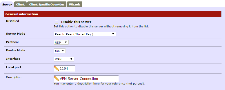
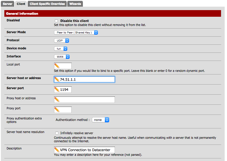
General Configuration
- Server Mode: Peer to Peer ( Shared Key )
- Protocol: UDP
- Device Mode: tun
- Interface: The interface the VPN will be coming in from. Most likely WAN
- Local Port: 1194
- Description: Put in any description name for the VPN connection.
Here is a screenshot of my General information section after filling in required information.
Router A (Server) Configuration
Make sure you are logged into Router A, the router acting as your OpenVPN Server, before proceeding.
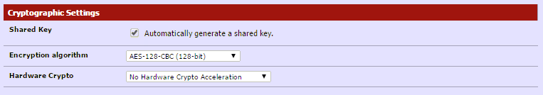
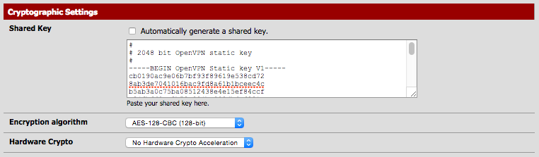
Cryptographic Settings
- Shared Key: Check the “Automatically generate a shared key” box.
- Encryption algorithm: AES-128-CBC (128-bit) Feel free to select another encryption algorithm, it just has to match on both sides (server/client).
- Hardware Crypto: No Hardware Crypto Acceleration.
Here is what mine looks like.
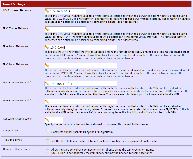
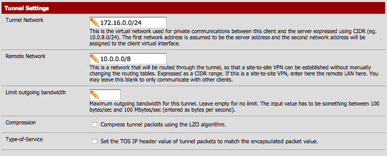
Tunnel Settings
- IPv4 Tunnel Network: 172.16.0.0/24 (any unused network is fine, this is only used for communication between the client and server)
- IPv4 Local Network: 10.0.0.0/8 (this is the local network on the server side).
- IPv4 Remote Network: 192.168.1.0/24 (this is the local network on the client side. If there are multiple clients/networks, separate them with a comma).
This is what mine looks like. You can enable compression if you like, but it’s not necessary. If only passing traffic that’s already compressed, such as http or ssh, it might add unnecessary overhead.
Advanced Configuration
There are no changes needed in the Advanced Configuration section. If needed, you can add additional route tables and OpenVPN commands here.
Click Save.
Now, click the “e” beside the connection you just created, and scroll down to Shared Key. A key will now be generated and show in that box. Highlight it, and copy it. You will need to paste it in the client shared key box in a minute.
Firewall Configuration (Router A, Server)
There are two rules we need to create in order for the VPN to work.
- WAN Rule: Allow incoming connections to port 1194, to the router itself. This allows incoming VPN connections.
- OpenVPN Rule: Allow all VPN traffic, so one side can communicate with the other.
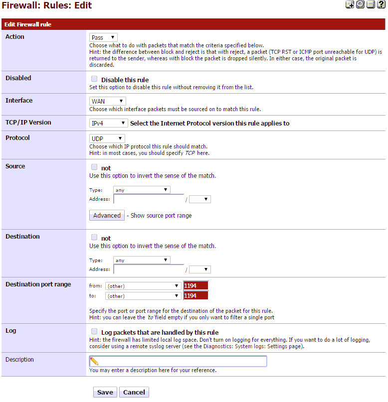
First, we will create the WAN rule. Go to Firewall > Rules, then select the WAN tab.
- Now, click on the + to add a rule.
- Action: Pass
- Interface: WAN
- Protocol: UDP
- Destination Port Range: From: 1194, To: 1194
- Click Save
- It should look like this.
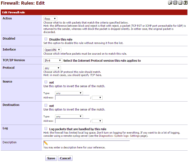
Next, click on the OpenVPN tab, under Firewall: Rules. Then click + to add a new rule.
- Action: Pass
- Interface: OpenVPN
- Protocol: Any
Go ahead and click Save.
It should look like this.
the server is now configured and ready to go.
Router B (Client) Configuration
Make sure you are now logged into Router B, the router you will be configuring as the OpenVPN Client. Navigate to VPN > OpenVPN, then select the Clients tab.
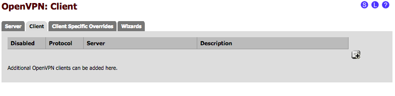
Under the Clients tab, select the + to add a new client.
General Information
- Server Mode: Peer to Peer ( Shared Key )
- Protocol: UDP
- Device Mode: tun
- Server host or address: 74.51.1.1 (this is the IP address of your WAN connection on Router A, the Server)
- Server Port: 1194
- Description: VPN Connection to Datacenter (Descriptive name of the VPN connection).
My General Information section looks like this.
Cryptographic Settings
- Shared Key: Uncheck this box, and Paste the key generated by your server. This can be found if you edit the OpenVPN server connection we created earlier (on Router A, Server), under the shared key section.
- Encryption Algorithm: AES-128-CBC (128-bit) (unless you selected a different encryption algorithm earlier. If so, select it.)
- Hardware Crypto: No Hardware Crypto Acceleration
My client Cryptographic Settings looks like this. (Shared Key has been changed for security)
Tunnel Settings
- Tunnel Network: 172.16.0.0/24 (this is the tunnel network that was entered on the server. If different, make sure it matches here.)
- Remote Network: 10.0.0.0/8 (this is the local network (LAN) of your OpenVPN server)
- Compression: Only enable this if you did so on the server configuration.
My Tunnel Settings looks like this.
Advanced Configuration
Just like on the server’s advanced configuration, the client’s should be left blank as well.
Click Save.
Now, we need to configure the firewall on the client side (Router B, Client).
Go to Firewall > Rules, then select the OpenVPN tab. Then click + to add a new rule.
- Action: Pass
- Interface: OpenVPN
- Protocol: Any
Go ahead and click Save.
It should look like this.

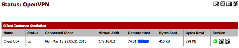
At this point, everything is set up and your VPN should be connected. The connection activates very quickly once the settings are correct. To see if the link is up, navigate to Status > OpenVPN. You want to look in the status column. It should be “up.”
It looks like this.

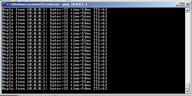
On the Router B (Client) local network, you should now be able to ping the LAN IP address of the Router A (server) LAN interface. In my case, 10.0.0.1.
Troubleshooting
If you are having problems pinging one direction or the other, go through these steps:
- Verify firewall settings on both the client and server side, using the information above.
- Try pinging both VPN tunnel addresses assigned to the client and the server. This will be the 172.16.0.x addresses. For some reason, i’ve seen the routing table not propagate correctly until these IP addresses are pinged. Weird, I know.
- Check the routing table on each PFsense router and make sure the VPN tunnel network is listed in the routing table. If not, start over and recreate the tunnel.