What is Traffic Shaper
- The basic idea of traffic shaping, raising and lowering the priorities of packets, or simply keeping them under a certain speed, is a simple one. However, the number of ways in which this concept can be applied is vast. These are but a few common examples that have proven popular with our users.
- The biggest problem on a shared network is that one user could potentially consume all of the available internet bandwidth and slow down the connections for all of the other users as a result. High-bandwidth users can create an even bigger problem if your network has critical traffic such as VOIP that depends on having enough bandwidth to function.
The solution to problems like this is to implement a traffic shaping system. Traffic shaping can prioritize your important or time critical network traffic to guarantee performance and at the same time throttle less important traffic.
In this hub I will show you how to use DefenceBolt, anopen source firewall, to configure traffic shaping to manage your networks bandwidth.
Keep Browsing Smooth
Asymmetric links, where the download speed differs from the upload speed, are common place these days, especially with DSL. Some links are so out of balance that the maximum download speed is almost unattainable because it is difficult send out enough ACK (acknowledgement) packets to keep traffic flowing. ACK packets are transmitted back to the sender by the receiving host to indicate that data was successfully received, and to signal that it is OK to send more. If the sender does not receive ACKs in a timely manner, TCP’s congestion control mechanisms will kick in and slow down theconnection.
You may have noticed this situation before: When uploading a file over such a link, browsing and downloading slows to a crawl or stalls. This happens because the uploading portion of the circuit is full from the file upload, there is little room to send ACK packets which allow downloads keep flowing. By using the shaper to prioritize ACK packets, you can achieve faster, more stable download speeds on asymmetric links.
This is not as important on symmetric links where the upload and download speed are the same, but may still be desriable if the available outgoing bandwidth is heavily utilized.
Reduce Gaming Lag
There are also options to give priority to the traffic associated with network gaming. Similar to prioritizing VoIP calls,the effect is that even if you are downloading while playing, the response time of the game should still be nearly as fast as if the rest off your connection were idle.
Keep P2P Applications In Check
By lowering the priority of traffic associated with known peer-to-peer ports, you can rest easier knowing that even if those programs are in use, they won’t hinder other traffic on your network. Due to its lower priority, other protocols will be favored over P2P traffic, which will be limited when any other services need the bandwidth.
Enforce Bandwidth Limits
Using limiters you can apply a bandwidth limit to a group of people, such as all traffic on an interface, or you can set masking on the limiters to apply them on a per-IP basis. This way you can ensure that no one person can consume all available bandwidth.
ALTQ Scheduler Types
In DefenseBolt there are more options available to cover alarger possible range of shaping scenarios. The new options for ALTQ are Class-Based Queueing (CBQ), which can do bandwidth sharing between queues and bandwidth limits, and Priority Queueing (PRIQ), which only does prioritization. Each of these isselectable in the shaper wizards,and the wizard will show the proper options and create the proper queues for you based on the chosen ALTQ discipline.
Performance Caveats
Enabling ALTQ traffic shaping places an extra burden on the hardware, and there will be an overall potential network performance loss. On systems that have horse power to spare, this may not be noticeable. On systems that operate close to their specification limits, then you may see a degradation of performance. Whether the loss is worse than working without shaping is up to your individual workload.
Local LAN-to-LAN Traffic
In old version the shaper could only apply to one LAN type interface, and the traffic between that LAN and other localnetworks would still be affected by the shaper and have it’s speed limited. In new version, the shaper now has a separate queue for this local traffic that will not limit it. Only traffic to and from the WAN to the LAN will be shaped.
Hierarchical Fair Service Curve (HFSC)
The HFSC traffic shaping discipline has been in DefenseBoltfor many years old version. it was the only available choice. It is a very powerful discipline, good for ensuring that services like VoIP and video are delivered a minimum guaranteed amount of bandwidth.
In HFSC, the queues are arranged in a hierarchy,or a tree, with root queues for each interface, parent queues underneath, and child queues nested under the parent queues (etc.). Each queue can have a set bandwidth and related options.
HFSC-specific Queue Options
Editing queues is not easy, and if you do not have a thorough understanding of the settings involved, it is best to leave the settings alone. That having been said, here are the options. Enable/Disable queue and its children and Queue Name are self-explanatory. Priority assigns a priority to the queue from 0 to 7 (7 is highest). The Queue limit field specifies the queue limit in packets per second. Next is Scheduler options; there are five different options here Editing queues is not easy, and if you do not have a thorough understanding of the settings involved, it is best to leave the settings alone.
Default Queue: Selects this queue as the default, the one which will handle all unmatched packets. Each interface should have one and only one default queue.
Random Early Detection (RED): This is a method to avoid congestion on a link; it will actively attempt to ensure that the queue does not get full. Ifthe bandwidth is above the maximum given for the queue, drops will occur. Also, drops may occur if theaverage queue size approaches the maximum. Dropped packets are chosen at random, so the more bandwidthin use by a given connection, the more likely it isto see drops. The net effect is that the bandwidth is limited in a fair way, encouraging a balance. RED should only be used with TCP connections; TCP is capable of handling lost packets and can resend when needed.
Random Early Detection In and Out (RIO): Enables RED with in/out, which will result in having queue averages being maintained and checked against forincoming and outgoing packets.
Explicit Congestion Notification (ECN): Along with RED, it allows the sending of control messages that will throttle connections if both ends support ECN. Instead of dropping the packets as RED will normally do, it will set a flag in the packet indicating network congestion. If the other side sees and obeys the flag, the speed of the ongoing transfer will be reduced.
CoDel Active Queue: A newish form of AQM (Active Queue Management) designed to solve at least in part the problem of bufferbloat (persistently full buffers). The three primary innovations of CoDel are: [1] using the local minimum queue as the queue measure; [2] simplified single-state variable tracking of how long the minimum has been above or below the target value for standing queue delay rather than keeping a window of values to compute the minimum; and [3] use of queue-sojourn time rather than measuring queue size in bytes or packets. This simple description does not do justice to the CoDel AQM.
The next two fields are fairly self-explanatory: at “Description“, you can enter a brief description, and at “Bandwidth“, you can specify the total bandwidth allocated to this queue. The options for “Service Curve” are interesting because they enable you to configure a Hierarchical Fair Service Curve (HFSC) for the queue. I covered HFSC in somewhat greater depth in a previous article, but here are the options in a nutshell:
For example, you need m1 bandwidth within d time, but with a normal maximum of m2. Within the time setby d, m1 is the maximum. After d milliseconds has expired, if the traffic is still above m2, it will be shaped. If you read my article about HFSC or any of the other material relating to it, you will see that m1 and m2 are two different slopes for the curve
Service Curve
HFSC supports a few queue options that are not supported by the other disciplines. It is through these options that it achieves its guaranteed real-time processing and link sharing.
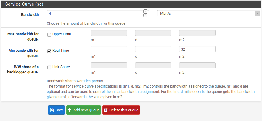
The Service Curve (sc) is where you can fine tune the bandwidth requirements for this queue.
- m1 Burstable bandwidth limit ( burst transmission or data burst is the broadcast of a relatively high-bandwidth transmission over a short period)
-d Time limit for bandwidth burst, specified in milliseconds. (e.g. 1000 = 1 second)
- m2 Normal bandwidth limit
The next two fields are fairly self-explanatory: at Description, you can enter a brief description, and at Bandwidth, you can specify the total bandwidth allocated to this queue. The options for Service Curve are interesting because they enable you to configure a Hierarchical Fair Service Curve (HFSC) for the queue. I covered HFSC in somewhat greater depth in a previous article, but here are the options in a nutshell:
Each of these values may be set for the followinguses:
Upper Limit Maximum bandwidth allowed for the queue. Will do hard bandwidth limiting. The m1 parameter here can also be used to limit bursting. In the time frame d you will not get more than m1 bandwidth.
Real Time Minimum bandwidth guarantee for the queue. This is only valid for child queues. The m1 parameter will always be satisfied in timeframe d, and m2 is the maximum that this discipline will allow to be used.
Note
The value for m2 cannot exceed 30% of the parent queue’s available bandwidth.
- Link Share The bandwidth share of a backlogged queue. Will share the bandwidth between classes if the Real Time guarantees have been satisfied. If you set the m2 value for Link Share, it will override the Bandwidth setting for the queue. These two settings are the same, but if both are set, Link Share’s m2 is used.
By combining these factors, a queue will get the bandwidth specified by the Real Time factors, plus those from Link Share, up to a maximum of UpperLimit. It can take a lot of trial and error, and perhaps a lot of arithmetic, but it may be worth it to ensure that your traffic is governed as you see fit. For more information on m1, d, and m2 values for different scenarios.
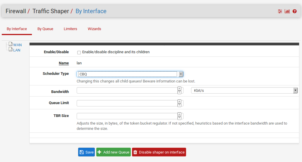
Class-Based Queueing (CBQ)
Class-Based Queueing, or CBQ, is similar to HFSC in that is can have a tree of queues nested under other queues. It supports bandwidth limits (not guarantees like HFSC), priorities for queues, and the ability to allow queues to borrow bandwidth from their parent. Because of the simpler queue configuration, it can be a good alternative to HFSC especially if you do not need to guarantee minimum bandwidths.
With CBQ, queue priorities range from 0 to 7, higher numbers indicating higher priority. Queues ofan equal priority are processed in a round-robin fashion.
Note
Though the child queues can borrow from their parent queue, the sum of the bandwidth of the child queues cannot exceed the bandwidth of the parent, so this is not an alternative to usinglimiters to apply individual (e.g. per-IP) bandwidth limits.
CBQ-Specific Queue Options
The CBQ discipline supports a the concept of borrow, meaning that if the checkbox on the queue is checked to Borrow from other queues when available, then it will be able to borrow other available bandwidth from its parent queue. This will only allow a child queue to obtain up to the bandwidth of its immediate parent, if available, it will not borrow from other parent queues.
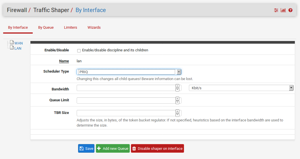
Priority Queueing (PRIQ)
PRIQ is one of the easiest disciplines to configure and understand. The queues are all directly under the root queue,there is no structure to have queues under other queues with PRIQ as there is with HFSC and CBQ. It does not care about bandwidth on interfaces, on the priority ofthe queues. The values for priority go from 0 to 15, and the higher the priority number, the more likely the queue is to have its packets processed.
PRIQ can be pretty harsh to lesser queues, starving them when the higher priority queues need the bandwidth. In extreme cases, it is possible for a lower priority queue to have little or no packets handled if the higher priority queues are consuming all available resources.
CoDel Active Queue Management
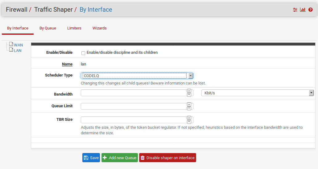
The CoDel Active Queue Management (AQM) discipline was recently added to DefenseBolt The name is short for Controlled Delay and is pronounced coddle. It was designed to combat some of the problems associated with buffer bloat in networking infrastructure. Buffer bloat is described in detail at http://www.bufferbloat.net/projects/bloat/wiki/Introduction. Basically, due to the size of buffers in network equipment, traffic can pile up and go in chunks rather than a smooth stream. By controlling the delay of the traffic this effect can be lessened.
CoDel has no specific configuration controls or options. When activated for a queue, it will automatically attempt to manage traffic as described in the CoDel wiki at http://www.bufferbloat.net/projects/codel/wiki. It attempts to keep traffic delays low but does permit bursting, it controls delays but it does not pay attention to round-trip delay, load, or link speed, and it can automatically adjust if the link speed changes.
The target for CoDel is mid-range networking. It does not work well at very low bandwidth (512Kbpsor less) and it does not gracefully handle large numbers of simultaneous flows or datacenter-gradetraffic loads.
Configuring the ALTQ Traffic Shaper With the Wizard
It is recommended that you configure the traffic shaper for the first time using the wizard, which will guide you through the process. Due to the complexity of the shaper queues and rules, it is not a good idea to attempt starting from scratch on your own. If you need custom rules, step through the wizard and approximate what you will need, then make the custom rules afterward. Each screen will setup unique queues, and rules that will control what traffic is assigned into those queues. Should you want to configure everything manually, simply specify your WAN speed at the first screen,then click Next through all the remaining screens without configuring anything.
Note
Going through the wizard and clicking Finish at the end will replace all of your shaper queues and floating rules created by the wizard, or cloned from wizard rules, with the queues and rules from the new wizard configuration.
Selecting a Wizard
To get started with the Traffic Shaping Wizard, click on Firewall Traffic Shaper, and click the Wizards tab. You will be presented with a list of currently available shaper wizards. As of this writing, those included:
Single LAN, Multi-WAN Used when you have only one LAN, and one or more WANs. The LAN interface for shaping is assumed to be the interface indicated by lan in the DefenseBolt interface assignments. The WAN interfaces are selectable.
Single WAN, Multi-LAN Used when you have only one WAN, and one or more LANs. The WAN interface for shaping is assumed to be the interface indicated by wan in the DefenseBolt interface assignments. The LAN interfaces are selectable.
Multiple LAN/WAN Used when you have one or more WANs and one or more LANs. WAN and LAN interfaces are selectable.
Dedicated Links Used when specific LAN+WAN pairings should be accounted for in the shaper configuration. WAN and LAN interfaces are selectable.
Note that the first three are very similar, and you can, in fact, use any of them and end up with the same result. As such we will only cover one of those in this chapter. If you only have a single LAN and a single WAN, you can use any of the three and simply enter 1 when prompted for how many interfaces you have of the LAN/WAN variety.
Starting the Wizard
Once you have selected the wizard you will use, and have clicked it, a the wizard starts and the first screen will then prompt for the number of connections that are variable in the wizard that was chosen. This step asks for the number of WANs, LANs, or both, as in Figure Entering the Interface Count. Enter the number of connections that you have, as prompted, and proceed through the wizard. As you finish each screen of the wizard, click Next butten.
Networks and Speeds
This screen, as shown in Figure Shaper Configuration,is where you configure the network Interfaces that will be the Inside and Outside from the point of view of the shaper, along with the Download and Upload speeds for a given WAN. When there is more than one interface of a given type, there will be multiple sections on the page to handle each one individually.
Aside from the interfaces and their speeds, you also need to select an ALTQ Scheduler (ALTQ Scheduler Types) for the WAN(s) and LAN(s). You will want to use the same scheduler on every interface.
Depending on your connection type, the true link speed may not be the actual usable speed. In the caseof PPPoE, you have not only PPPoE overhead, but also overhead from the underlying ATM network link being used in most PPPoE deployments. By some calculations, between the overhead from ATM, PPPoE, IP, and TCP, you may lose as much as 13% of the advertised link speed. When in doubt of what to set the speed to, be a little conservative. Reduce by 10-13% and work your way back up to larger values. If you have a 3Mbit/s line, set it for about 2.7 ‘‘Mbit/s and try it. You can always edit the resulting parent queue later and adjust the speed. If you set it low, the connection will be maxed out at exactly the speed you set. Keep nudging it up higher until you no longer get any performance gains.
The interface speeds can be specified in Kbit/s , Mbit/s , or Gbit/s .
put image
Voice over IP
There are several options available for handling VoIP call traffic, shown in Figure Voice over IP. The first choice, Prioritize Voice over IP traffic, is self-explanatory. It will enable the prioritization of VoIP traffic and this behavior can be fine-tuned by the other settings on the page. There are a few well-known providers including Vonage, Voice pulse, PanasonicTDA, and Asterisk servers. If you have a different provider, you can choose Generic , or override this setting with the Address field by entering the IP of your upstream PBX or SIP trunk, or an alias containing the IPs or networksfor them.
You may also choose the amount of Bandwidth to guarantee for your VoIP phones. This will vary based onhow many phones you have, and how much bandwidth each session will utilize.
Note
The bandwidth reservation for a service such as VoIP cannot exceed 30% of the available bandwidth on the link. For example, on a 1Mbit/s link, you cannot reserve more than 300Kbit/s.
Note
The way the shaper matches traffic with floating rules, it works best to use the remote SIPtrunk or PBX because otherwise it may not be able to match the traffic properly. If you use the IPs of the phones it may only match traffic in one direction, or not at all.
Penalty Box
The penalty box, depicted in Figure Penalty Box, is a place to which you can relegate misbehaving users or devices that would otherwise consume more bandwidth than desired. These users are assigned a hard bandwidth cap which they cannot exceed. Check the Penalize IP or Alias to enable the feature, enter an IP or Alias in the Address box,
put image
Peer-to-Peer Networking
The next screen, shown in Figure Peer-to-Peer Networking, will let you set controls over many peer-to-peer (P2P)networking protocols. By design, P2P protocols will utilize all available bandwidthunless limits are put in place. If you expect P2P traffic on your network, it is a good practice to ensure that other traffic will not be degraded due to its use. To penalize P2P traffic, first check Lower priority of Peer-to-Peer traffic.
Many P2P technologies deliberately try to avoid detection. Bittorrent is especially guilty of this behavior. It often utilizes non-standard or random ports, or ports associated with other protocols. You can check the p2pCatchAll option which will cause any unrecognized traffic to be assumed as P2P traffic and its priority lowered accordingly. You can set hard bandwidth limits for this traffic underneath the catchall rule. The upload and download bandwidth limits are set in Kilobits per second.
The remaining options are comprised of various known P2P protocols, more than 20 in all. Check each one that you would like to be recognized.
Network Games
Many games rely on low latency to deliver a good online gaming experience. If someone tries to download large files or game patches while playing, that traffic can easily swallow up the packets associated with the game itself and cause lag or disconnections. By checking the option to Prioritize network gaming traffic, as seen in Figure Network Games,
you can raise the priority of game traffic so that it will be transferred first and given a guaranteed chunk of bandwidth
There are many games listed, check all those which should be prioritized. If your game is not listed here you may still want to check a similar game so that you will have a reference rule that may be altered later.
put image
Raising or Lowering Other Applications
The last configuration screen of the shaper wizard, seen in Figure Raise or Lower Other Applications, lists many other commonly available application and protocols. How these protocols are handled will depend on the environment that this DefenseBolt router will be protecting. Some of these may be desired, and others may not. For example, in a corporate environment, you may want to lower the priority of non-interactive traffic such as mail, where a slow down isn’t noticed by anyone, and raise the priority of interactive services like RDP where poor performance is an impediment to people’s ability to work. In a home, multimedia streaming may be more important, and other services can be lowered. Enable the option for Other networking protocols, and then pick and choose from the list.
There are more than 25 other protocols to choose from, and each can be given a Higher priority , Lower priority , or left at the Default priority . If you enabled p2pCatchAll, you will want to use this screen to ensure that these other protocols are recognized and treated normally, rather than penalized by the default p2pCatchAll rule.
put image
Finishing the Wizard
All of the rules and queues will now be created, but not yet in use. By pressing the Finish button on the final screen, the rules will be loaded and active.
Shaping should now be activated for all new connections. Due to the state full nature of the shaper, only new connections will have traffic shaping applied. In order for this to be fully active on all connections, you must clear the states. To do this, visit Diagnostics States, click the Reset States tab, check Firewall statetable, then click Reset.
Monitoring the Queues
In order to be sure that traffic shaping is working as intended, it may be monitored by browsing to Status Queues. As can be seen in Figure Basic WAN Queues, this screen will show each queue listed by name, its current usage, and some other related statistics.
put image
The graphical bar shows you how full a queue is. The rate of data in the queue is shown in both packets per second (pps) and bits per second (Kbps). Borrows happen when a neighboring queue is not full and capacity is borrowed from there when needed. Drops happen when traffic in a queue is dropped in favor of higher priority traffic. It is normal to see drops, and this does not mean that a full connection is dropped, just a packet. Usually, one side of the connection will see that a packet was missed and then resend, often slowing down in the process to avoid future drops. The suspends counter indicates when a delay action happens. The suspends counter is only used with the CBQ scheduler, and should be zero when other schedulers are in use.
Advanced Customization
After using the shaper wizard, you may find that the rules it generates do not quite fit your needs. You may want to shape a service that is not handled by the wizard, a game that uses a different port, or there may be other services that need limited. Once the basic rules have been created by the wizard, it should be relatively easy to edit or copy those rules and create custom ones of your own.
Editing Shaper Queues
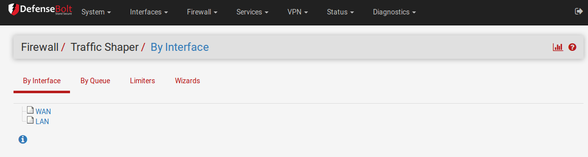
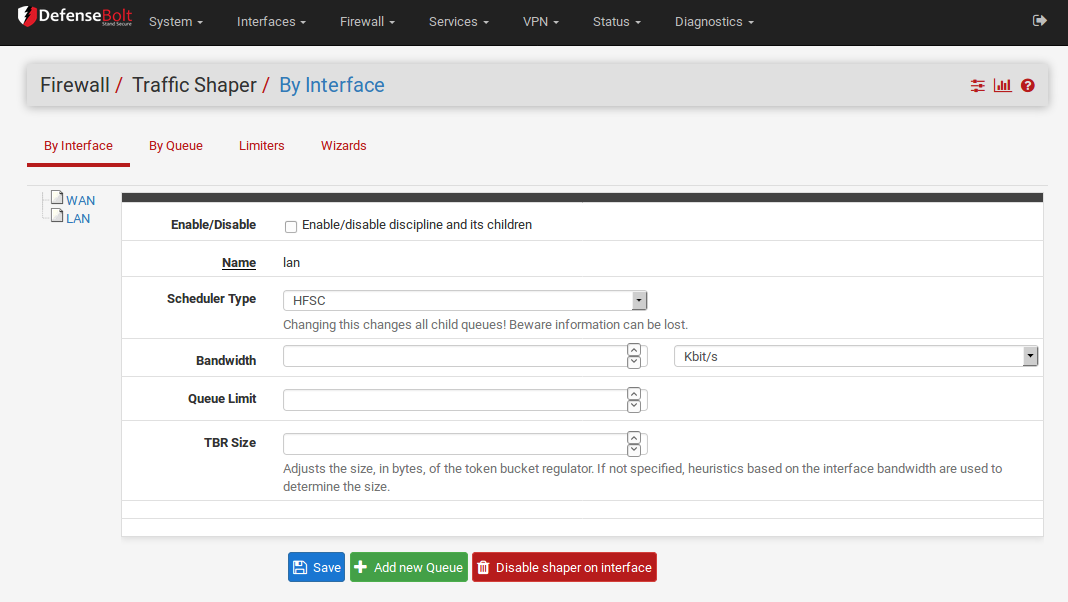
As mentioned in the summary, the queues are where bandwidth and priorities are actually allocated. Each queue will have settings specific to the scheduler that was chosen in the wizard, as mentioned earlier in ALTQ Scheduler Types. The queues can also be assigned other attributes that control how they behave, such as being low-delay, or having certain congestion avoidance algorithms applied. Queues may be changed by going to Firewall Traffic Shaper, and clicking on the queue names in the list or tree shown on the By Interface or By Queue tabs, like the one in Figure Traffic Shaper Queues List
Editing queues is not for the weak of heart. It can be a complex task with powerful results, but without thorough understanding ofthe settings involved, it is best to stick with the queues generated by the wizard and alter their settings, rather than trying to make new ones from scratch.
To edit a queue, click its name in the list/tree. To delete a queue click it once to edit it, then click Delete This Queue. You should not attempt to delete a queue if it is still being referenced by a rule. To add a new queue, click the interface or parent queue under which the new queue will live, and then click Add New Queue.
When editing a queue, each of the options should be carefully considered. If you are looking for more information about these settings than is mentioned here, visit the PF Packet Queueing and Prioritization FAQ or read in The OpenBSD PF Packet Filter book.
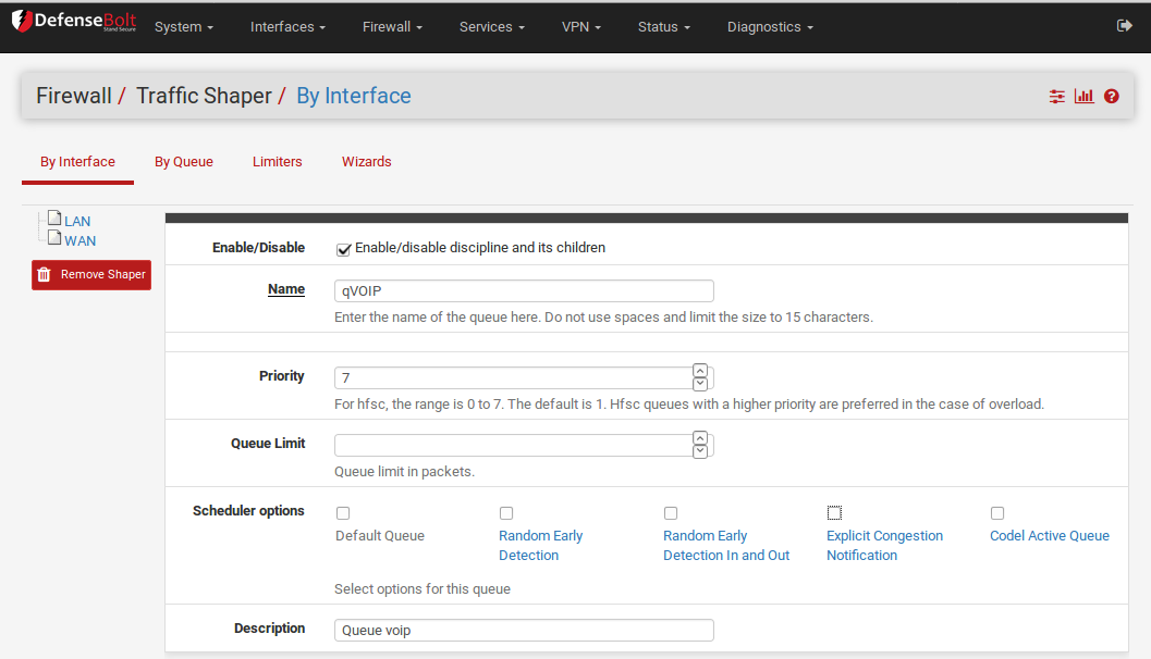
The Queue Name must be between 1-15 characters and cannot containspaces. The most common convention is to start the name of a queue with the letter “q” so that it may be more readily identified in the ruleset.
Priority can be any number from 0-7 for CBQ and 0-15 for PRIQ. Though HFSC can support priorities, the current code does not honor them when performing shaping. Queues with higher numbers are preferred when there is an overload, so situate your queues accordingly. For example, VoIP traffic should be of the highest priority,so it should be set to a 7 on CBQ or 16 on PRIQ. Peer-to-peer network traffic, which can be delayed in favor of other protocols, should be set at 1.
The Queue Limit can set a packets per second limit on a queue, but is typically left blank. This is an alternate way to limit throughput.
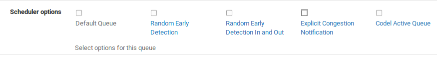
There are four different Scheduler options that may be set for a given queue:
Default Queue Selects this queue as the default, the one which will handle all unmatched packets. Each interface should have one and only one default queue.
Random Early Detection (RED) A method to avoid congestion on a link; it will actively attempt to ensure that the queue does not get full. If the bandwidth is above the maximum given for the queue, drops will occur. Also, drops may occur if the average queue size approaches the maximum.
Dropped packets are chosen at random, so the more bandwidth in use by a given connection, the more likely it is to see drops. The net effect is that the bandwidth is limited in a fair way, encouraging a balance. RED should only be used with TCP connections since TCP is capable of handling lost packets, and can resend when needed. Random Early Detection In and Out (RIO) Enables RED with in/out, which will result in having queue averages being maintained and checked against for incoming and outgoing packets.
Explicit Congestion Notification (ECN) Along with RED it allows the sending of control messages that will throttle connectionsif both ends support ECN. Instead of dropping the packets as REDwill normally do, it will set a flag in the packet indicating network congestion. If the other side sees and obeys the flag, the speed of the ongoing transfer will be reduced.
The Description of the queue is up to you. It may be left blank, or filled with some text to explain the purpose of the queue.
The Bandwidth setting should be a fraction of the available bandwidth in the parent queue, but it must also be set with an awareness of the other neighboring queues. When using percentages, the total of all queues under a given parent cannot exceed 100%. When using absolute limits, the totals cannot exceed the bandwidth available in the parent queue.
Next are the scheduler-specific options. They change depending onwhether you have chosen HFSC, CBQ, or PRIQ. They are all described in ALTQ Scheduler Types.
Click Save to save the queue settings and return to the queue list, then click Apply Changes to reload the queues and activate the changes.
Editing Shaper Rules
Traffic shaping rules control how traffic is assigned into queues. If a packet matches a traffic shaper rule, it will be assigned into the queue specified by that rule. Packet matching is handled by firewall rules, notably on the Floating tab. To edit the shaper rules, go to Firewall Rules, and click the Floating Tab. On that screen, shown in Figure Traffic Shaper Rules List, the existing rules will be listed with the usual firewall rule attributes, including the Queues used by the rules. You may apply queues on rules on other tabs, but the wizard only makes rules on the Floating tab using the match action that does not affect the pass/block action, it only queues traffic. For more information on floating rules, see Floating Rules for more information on floating rules, and Configuring firewall rules for information on firewall rules in general. Because these rules are just like any other rules, you can match any way in which you are familiar.
put image
Limiters
Limiters are a new method of traffic shaping, introduced in DefenseBolt 2.0 under Firewall Traffic Shaper on the Limiters tab. Limiters use dummynet(4) to enact bandwidth limits and perform otherprioritization tasks, among other things.
Limiters are currently the only way to achieve per-IP bandwidth limiting in DefenseBolt Limiters have actually been in use for a lot longer on pfSense aspart of the Captive Portal’s per-user bandwidth limits, but in 2.0 they have been hooked into pf so that they may be usedon their own with normal firewall rules, outside of Captive Portal.
Like HFSC and CBQ, Limiters may be nested with queues inside other queues. Root-level limiters (Also called Pipes), may have bandwidth limits and delays, while child limiters (Also called queues), may have priorities (Also called weights). Bandwidth limits canbe optionally masked by either the source IP or the destination IP, so that the limits can be applied per-IP instead of as a group.
Limiters are almost always used in pairs, one for incoming traffic and one for outgoing traffic.
The dummynet(4) system was originally designed, according to its man page, as a means to test TCP congestion control, and it grew up from there. Due to this purpose, a unique feature of limiters is that they can be used to induce artificial packet loss and delay into network traffic. That is primarily used in troubleshooting and testing (or being evil and playing a prank on someone), andnot often found in production.
Uses for Limiters
The primary use for limiters is applying bandwidth limits for users or specific protocols, e.g. Maximum of 1Mbit/s for SMTP, or “Pritam’s PC only can use 5bit/s”. It can also apply a per-IP limit, such as “All Users in 192.168.56.3/24 can each use a maximum of 3Mbit/s each”. Limiters are the only shaper type currently in DefenseBolt capable of such oversubscription. The ALTQ shaper requires all child queues to sum up to no more than the speed of theparent queue, but masked limiters let you give a set limit to as many IPs as you can funnel through the limiter.
Another use for limiters is to apply a group limit for a chunk ofyour network, such as “All users in 192.168.56.101/24 can use a maximum of 5Mbit/s total” or “Do not let Bob the Bittorrent Guy use more than 2Mbit/s”.
Limiters can also be used in a roundabout way to reserve bandwidth by limiting everything except a protocol you want to consume all bandwidth. In this type of setup on a 10Mbit/s link you’d pass traffic from, for example, a SIP server with no limiter, but thenhave a pass rule for all other traffic that gets a limit appliedfor 8Mbit/s. This would let the SIP server use all of the bandwidth it wanted, but it would always have at least 2Mbit/s, assuming the link speed is reliable/constant.
How Limiters Work
Limiters, like ALTQ, hold traffic to a certain point by dropping or delaying packets to achieve a specific line rate. Usually a protocol’s built-in mechanisms will detect the loss and back off to a speed it can sustain.
In situations where packets are queued under the same parent pipe, their weights are considered when ordering the packets before they are sent.
Unlike priorities in ALTQ’s CBQ and PRIQ, the weight of a queue in a limiter will never cause it to starve for bandwidth.
Creating Limiters
Limiters are managed under Firewall Traffic Shaper on the Limiters tab. To create a new root-level limiter (pipe), To create a child limiter (queue), click the limiter under which it can be created, and click Add New Queue. You will nearly always want to use limiters in pairs at the same level (e.g. two pipes, or two queues), one for inbound traffic and one for outbound traffic, so keep that in mind when creating them.
Enable Check the box to enable this limiter. If the limiter is disabled, it will not be available as a choice to be used on firewall rules.
Name This defines the Name of the limiter, as it will appearfor selection on firewall rules. The name must be alphanumeric, and may also include - and‘_‘. When choosing a name, it is best toavoid using In and Out since the same limiter, if used on both WAN and LAN, would be used in the In direction on one interface and the Out direction on another. It is better to instead use * Down or Download, and Up or Upload, but ultimately the naming convention can be anything you like,
Bandwidth (Pipes) This section lets you define a bandwidth value for the pipe, or multiple bandwidths if schedules are involved. This option does not appear when editing a child limiter (queue).
Bandwidth The numerical part of the bandwidth for the pipe, e.g. * 3 or 500.
Burst The Burst parameter specifies a total amount of data that can be transmitted without a limit applied after a period of idle time. This is not a rate, but a size. For example, if set to2MB, then the user will transmit 2MB of data at full speed, and once that bursting data size has been sent, the rate will be cut down to the limit specified in the Bandwidth field from that pointuntil the limiter goes idle again. To disable bursting, enter a 0 here.
Bw Type The units to be applied to the Bandwidth field, such as Bit/s , Kbit/s , Mbit/s , or Gbit/s .
Mask This drop-down selection controls how the addresses in the limiter are masked. If left set to none, then no masking will be performed, and the pipe bandwidth will be applied to all traffic in the group as a whole. If Source Address or Destination Address are chosen, then the pipe’s bandwidth limit will be applied on a per-IP basis (or a subnet basis, depending on the masking bits), using the direction chosen in the masking. In general, you’ll want to mask the Source Address on In (Upload) limiters for LAN-type interfaces, and Destination Address on Out (Download) limiters on LAN-type interfaces. Similar to swapping the directionality of the limiters when applying to LAN and WAN, masking is swapped as well, so the same masked limiter that is In on LAN would be used Out on WAN. There are separate boxes to control the exact masking of addresses in the limiter. the IPv4 mask bits were always 32 fora Per-IPv4-address limit. This is the most common usage. For a per- IPv6-address limit, use 128 as the IPv6 mask bits value. If you wish to make per-subnet or similar masks, enter the subnet bits in the appropriate box for either IPv4 or IPv6 mask bits, such as 24 to limit in groups of /24 subnets.
Description The Description, as usual, is an optional bit of text for your reference to explain the purpose for this Limiter.
Advanced Options There are some additional options that vary whether you’re editing a pipe or a queue, click Show Advanced Options and they will appear.
Delay (Pipes) The Delay option is only found on limiter pipes. It introduces an artificial delay (latency), specified in milliseconds, into the transmission of any packets in the limiter pipe. This is typically left blank so that packets are transmitted as fast as possible. This can be used to simulate high-latency connections such as satellite uplinks for lab testing.
Weight (Queues) The Weight option is only found on child limiters (queues). This value can range from 1 to100. Higher values give more precedence to packets that are in a given queue. Unlike PRIQ and CBQ priorities, a lowly weighted queue is not in danger of being starved of bandwidth.
Packet loss rate Another method of artificially degrading traffic,the Packet Loss Rate, can be configured to drop a certain fraction of the packets that enter the limiter. The value is expressed as a decimal representation of a percentage, so 0.01 is 1%, or one packet out of a hundred dropped. As with the other fields,it is normally left empty so every packet is delivered.
Queue Size Sets the size of the queue, specified in queue slots, used for handling queueing delay. Left blank, it defaults to 50, which is the recommended value. Slow speed links may need a lower queue size to operate efficiently.
Bucket Size The Bucket Size, also specified in slots, sets the size of the hashtable used for queue storage. The default value is 64. It must be a numeric value between 16 and 65536, inclusive.
For more information about these values, you can also look at theipfw(8) man page, in the section titled “Traffic Shaper (Dummynet) Configuration”.
Assigning and Using Limiters
Limiters are assigned using firewall rules, using the In/Out selectors in the advanced options section of the firewall rule. Any potential matching criteria you can express in a rule can be used to assign traffic to a limiter.
The most important thing to remember when assigning a limiter to a rule is that the In and Out fields are designated from the perspective of the firewall itself. For example, in a single LAN single WAN setup, inbound traffic on a LAN interface is actually going toward the Internet, i.e. uploaded data. Outbound traffic on the LAN interface is going toward the client PC, i.e. downloaded data. When considering the WAN interface, the directionality is reversed; Inbound traffic is coming from the Internet to the client, and outbound traffic is going from the client to the Internet.
In most cases, both an In limiter and Out limiter will be selected, but you can choose to select only one if traffic should be limited in a single direction.
Limiters may be applied on normal interface rules, or on floatingrules, even using the same Match action that can be used by ALTQ.
Checking Limiter Usage
Information about active limiters may be found under Diagnostics Limiter Info. Here, each limiter and child queue is shown, in text format. Each limiter’s set bandwidth and parameters are displayed, along with the current traffic level moving inside the limiter. In the case of masked limiters, the bandwidth of each IP address is shown.
In the future, there will be an easier-to-read graphical representation of this limiter information. For now, having access to theraw information is useful until that particular feature has been completed.
Layer 7 Inspection
Layer 7 inspection (L7) is, in simple terms, pattern matching to see if traffic matches a specific protocol such as HTTP, FTP, Bittorrent, etc. It compares packets against a given pattern that expresses how traffic for a protocol should look, and if it finds a match, then it applies an action to the connection. In some places this is also known as Deep Packet Inspection (DPI). In pfSense, Layer 7 inspection can be used for traffic shaping using ALTQ or for blocking traffic.
Entries that contain patterns to match for Layer 7 inspection arecalled Layer 7 containers. These containers are maintained at Firewall Traffic Shaper on the Layer 7 tab.
Heavy CPU Requirements / Performance Penalty
Layer 7 inspection involves putting every packet that matches a specific rule through an inspection daemon. Not only is extra delay introduced because the packets are routed through a daemon, there is also overhead from running a pattern match on the payload of every packet involved. As such, depending on the amount of traffic you are inspecting, CPU used can drastically increase. Layer 7 will reduce your overall potential throughput. The only way around it is to use a more powerful CPU, but even that has its limits.
Limitations
Layer 7 can help identify traffic, but there are some things it cannot do, such as:
- Matching encrypted traffic is not currently possible. If a user encrypts their traffic, such as Bittorrent, it can sidestep a layer 7 match.
- Some protocols vary too much to be reliably identified. Notable examples of this are Bittorrent and Skype. As aspects of the protocol change, new patterns may be needed.
- As mentioned previously, there is a heavy burden on the CPU to perform Layer 7 inspection.
- There is no affirmative case for protocol enforcement; HTTP traffic can be matched to be queued or blocked, but Layer 7 inspection cannot be used to ensure that only HTTP traffic is traveling on port 80.
- Layer 7 inspection cannot be used for routing or multi-wan decisions. By the time Layer 7 has identified a protocol, the connection has already been established, so it may not be re-routed along an alternate path.
- It is still necessary to pass traffic into Layer 7 inspection in order to for it to be processed. If a protocol hops between ports, such as Bittorrent, you would have to pass all traffic on all ports through Layer 7 inspection, at a great cost to your CPU, and if someone encrypts the protocol then it still can evade beingmatched.
Layer 7 Patterns
The heart of how Layer 7 matching works are regular expression (regex) patterns that are compared to each packet queued up for inspection
Creating Layer 7 Containers
To create a new Layer 7 container, go to Firewall Traffic Shaper and click the Layer 7 tab. From there, click add a new container.
Enable/Disable This checkbox controls whether or not the container is active and selectable on firewall rules.
Name The name of the container, as it will appear for selection on firewall rules. The name must be alphanumeric, and may also include - and _.
Description An optional bit of text for your reference, to describe the purpose of this container.
Rules The container may have one or more rules. Each pattern will be checked and the appropriate action applied to the packets flowing through the container. To add a new rule,
Pattern The name of file containing the match parameters for a given protocol or type of traffic, e.g. Bittorrent , smb , or http .
Structure The Structure option controls what type of behavior will occur once a pattern match has been found. The possible choices are: action for a firewall action, queue to place traffic into an ALTQ queue, and limiter to send traffic through a limiter.
Behavior This option controls the behavior that is dictated by the. Structure of this rule. For an action structure, the only choice is to block. For queue structures, all available ALTQ queues are listed. For limiter , all enabled limiters are listed.
Using Layer 7 Containers
Using a layer 7 container is a little counter-intuitive. As with other features, you enact them via firewall rules, however with a Layer 7 container, even if you want to block the traffic, you still use the pass action on the firewall rule.
The reason for this is due to how layer 7 inspection works. The rule passes the packet into the layer 7 container, and the container itself makes the decision to pass, block, queue, or limit the traffic based on whether or not a match was found.
To use a layer 7 container on a rule, first make sure it is a pass rule, and then choose the desired Layer 7 entry in the Layer 7 option of the rule, at the end of the Advanced Features section of the firewall rule edit screen.
Uploading New Patterns
New patterns can be uploaded by clicking the link at the bottom of Firewall Traffic Shaper on the Layer 7 tab. Before you can upload a pattern file, you have to first create one in the proper format, or download one from another source that is already in the proper format. For some examples, you can look in /usr/local/share/protocols/, the DefenseBolt repository on Github, or the L7-filter project page linked earlier in this section.
Once you have crafted or located your custom pattern, visit the upload page, click browse, locate your pattern file, and select it. Once the file has been selected, click Upload Pattern File and the new pattern will be available for selection when editing a Layer 7 container.
Traffic Shaping and VPNs
The following discussions pertain largely to ALTQ shaping. Limiters will work fine with VPNs as they would with any other interface and rules. Only the ALTQ shaper requires special consideration.
Traffic shaping with VPNs is a tricky topic because of how the VPN traffic is considered separate from, but also a part of, the WAN traffic through which it also flows. If WAN is 10 Mbit/s, then the VPN can also use 10Mbit/s, but there is not actually 20Mbit/s of bandwidth to consider, only 10Mbit/s. Assuch, it is more reliable to use methods of shaping that focus more on prioritization than bandwidth, such as PRIQ orin some cases, CBQ.
If the VPN contains only traffic that should be prioritized, then it is enough to consider only the VPN traffic itself on WAN, rather than attempting to queue traffic on the VPN as well as WAN. In these cases, you will need a floating rule on WAN to match the VPN traffic itself. The exact type of traffic varies depending on the type of VPN. IPsec and PPTP can both be prioritized by the shaper wizard, and these rules can be used as an example to match other protocols.